In 2017 these three posters were commissioned by the University of Wisconsin IoT Research Lab to demonstrate concepts of Internet of Things security. The three posters demonstrate 1) security vulnerabilities associated with sensors, and how a hack at each level of the chain might impact sensor data 2) security vulnerabilities with controllers, and how hacking any level can have an impact on door locks, HVAC units, or other devices, and 3) the broad impact of a compromised device and how multiple compromised devices can be used to attack assets on the Internet.
I built everything myself, including the design of all the 3D printed parts, the design of the poster, and the firmware running on a Raspberry Pi.
This project uses an ATTiny to control WS2812 LED strips. The strips are waterproof, and the embedded PCB and connector are as well. Up to 60 LEDs can be on each strip, and they cycle different modes on a power cycle or button press. This way they can all be synchronized to the same mode.
A science museum needs interactive exhibits, and this is an exhibit that can easily be extended, is easy to setup and install, is robust and safe and easy to maintain. Exhibits can easily cost tens of thousands of dollars, but this one can grow to any size budget but the top of the line is still under $4k. The idea is a periodic table of motion, where each cell, instead of an element, is a type of mechanical motion. Inside the cell is a description of the motion, a button to activate it, and an actual example of a working machine that uses the principle. Simple machines (lever, pulley, gear, etc.) are at the top of each column, and they increase in complexity. For an example of the variety of types of motions I want to capture and show off, see http://507movements.com. This project is very educational and interactive, and distills the basics of mechanics into individual and easy to understand concepts, building on them to show advanced motion mechanisms.
Originally intended for Burning Man, this device has usefulness more and more in our world as people embrace biking. Cars have had this feature for years; push the button on your keys and the car honks and the headlights flash. Why can’t we have that for bikes? This devices use a long range Bluetooth Low Energy module so you can find your bike from up to 100 yards away. Customizable flash patterns, remotes paired to your own anglerfish, waterproof, and you can ride in style with a blinky to alert traffic and passersby of your awesomeness.
My hackerspace Sector67 was approached this winter with a problem; the local minor league baseball stadium (Madison Mallards) fast pitch sign was old and no longer working, and they wanted some help fixing it up. In exchange for our expertise, they promised significant advertising and publicity, and they would have us be special guests at a ‘maker’ day during the season.
For the impatient, here’s the finished product:
We took them up on the offer and had a field trip to the stadium to see what was already there. There are two main parts to this project. First, there’s the sign itself. Second, there’s the press box, where the radar gun and the sign controller sit. The previous method was to have the person running the scoreboard watch the radar gun and type the speed onto a controller. There was no accounting for the angle of the radar gun, and it required a person to act as the middle man. They wanted to automate this part of the process. With the sign, they wanted it to work again. After seeing their existing setup, it didn’t take long for us to decide they needed an upgrade and we would start from scratch.
The sign in right field. Doesn’t look very big from this shot, but it’s legible from the far side of the stands.
Up close you can see it’s a bunch of incandescent bulbs. They’re not even covered! I wouldn’t want to run into that sign while catching a ball.
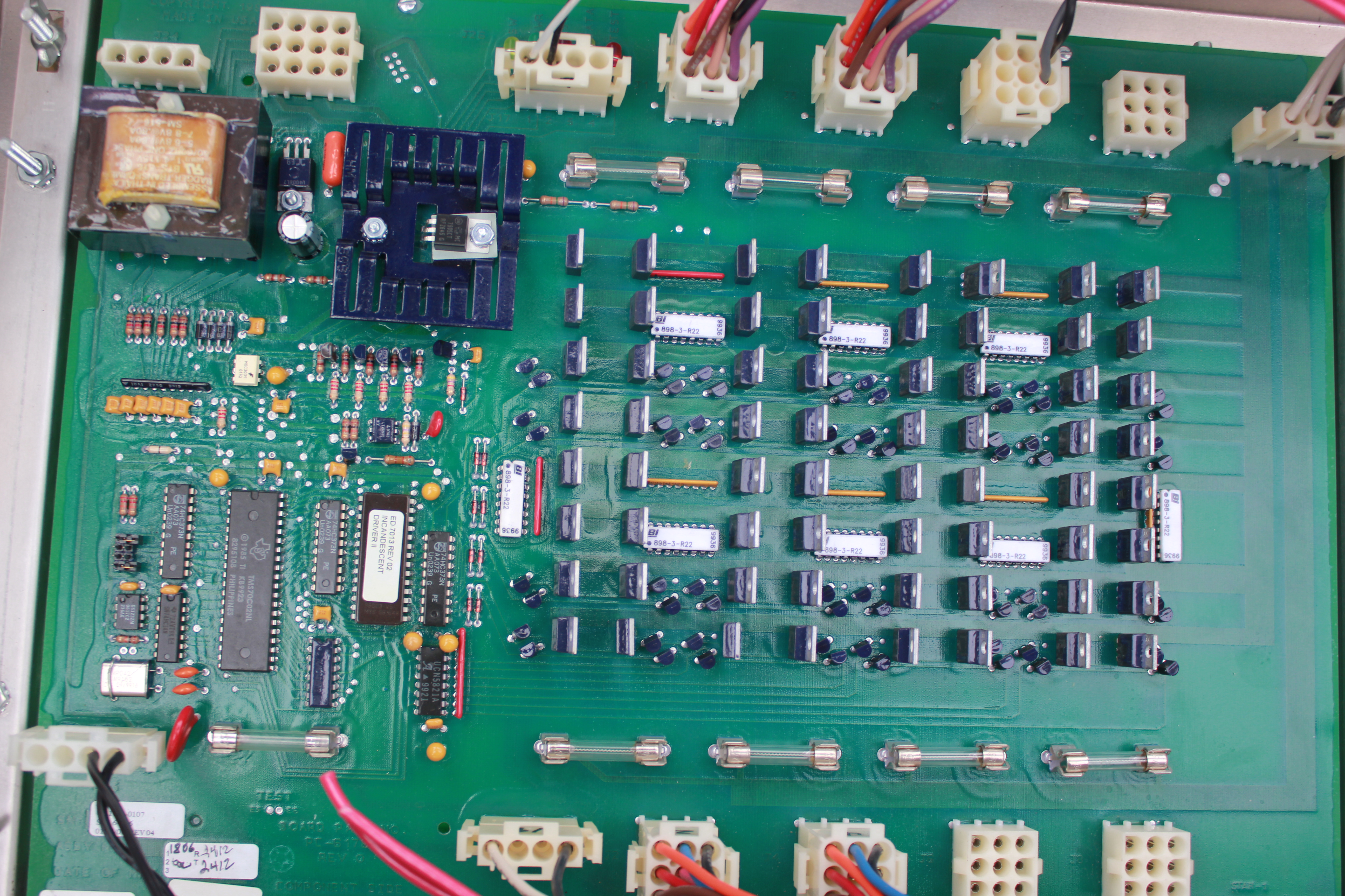
The electronics controlling the sign. This is basic and ancient stuff here.
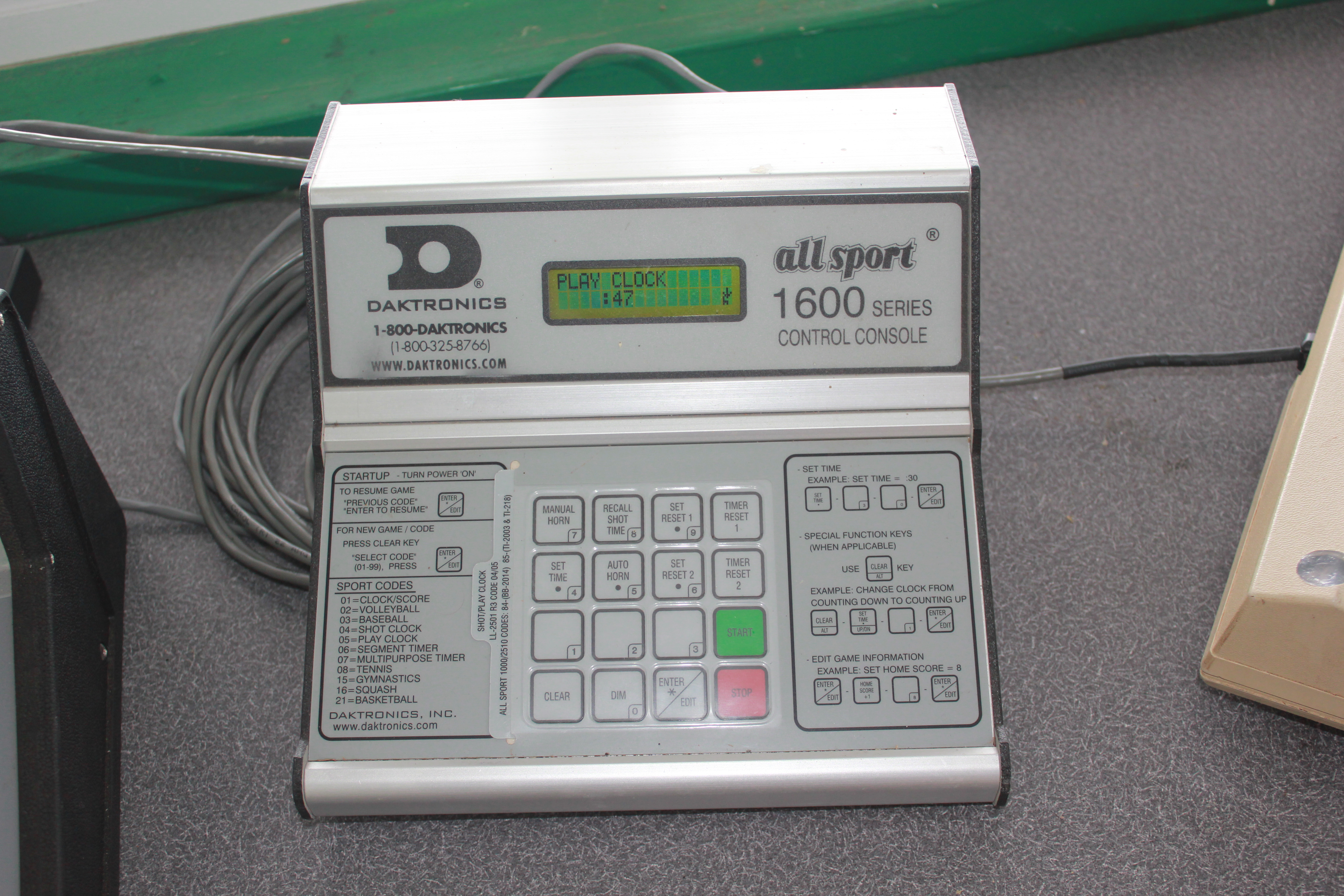
Up in the press box, this is what controls the sign.
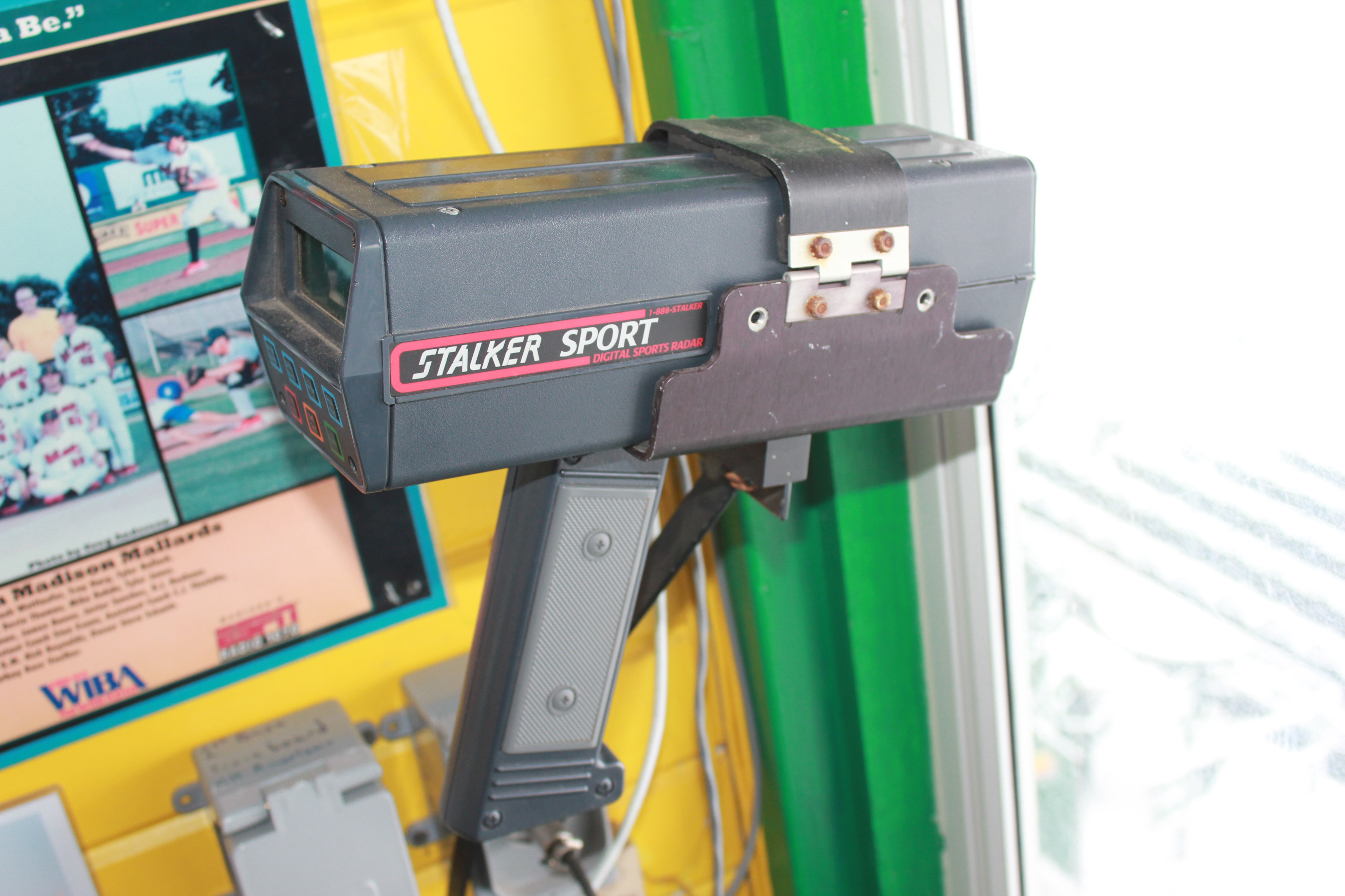
This is the radar gun. They have to charge up the battery (the handle) before every game. This is a pain.
The stadium let us borrow the radar gun, the only part of the process we intended to keep. Reverse engineering it wasn’t too bad. We were able to find a manual and figure out that the three pins coming out into the handle were two for the battery and one for a serial signal. Once we connected to this signal, it was trivial to decipher it (9600 baud ASCII text). We designed a 3D printed part that would take the place of the handle and supply power to the radar gun as well as grab the serial signal.
Yes, those are nails. They worked perfect.
After that was the box to replace the controller. This box would read in the serial signal, compensate for the angle, and send out a signal to the sign. At first we played with XBee for a wireless transfer. This ended up being so unreliable and so difficult to get set up that we decided to give up. Besides, long term support is important for this kind of a project, and something wireless is a lot more difficult to diagnose and debug than wired. So we went with RS485, which is perfect for long distances, and there was already a pre-existing cable from the previous sign. I threw in a screen and some buttons for good measure (to let the user adjust the angle), and a switch to turn it all on, and we were good to go. Now the only thing a user has to do is flip the switch to turn it on, then push the power button on the radar gun, and it works.
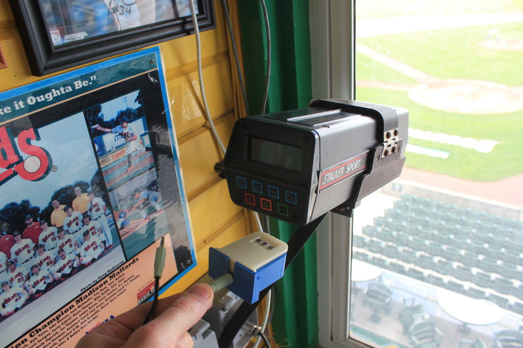
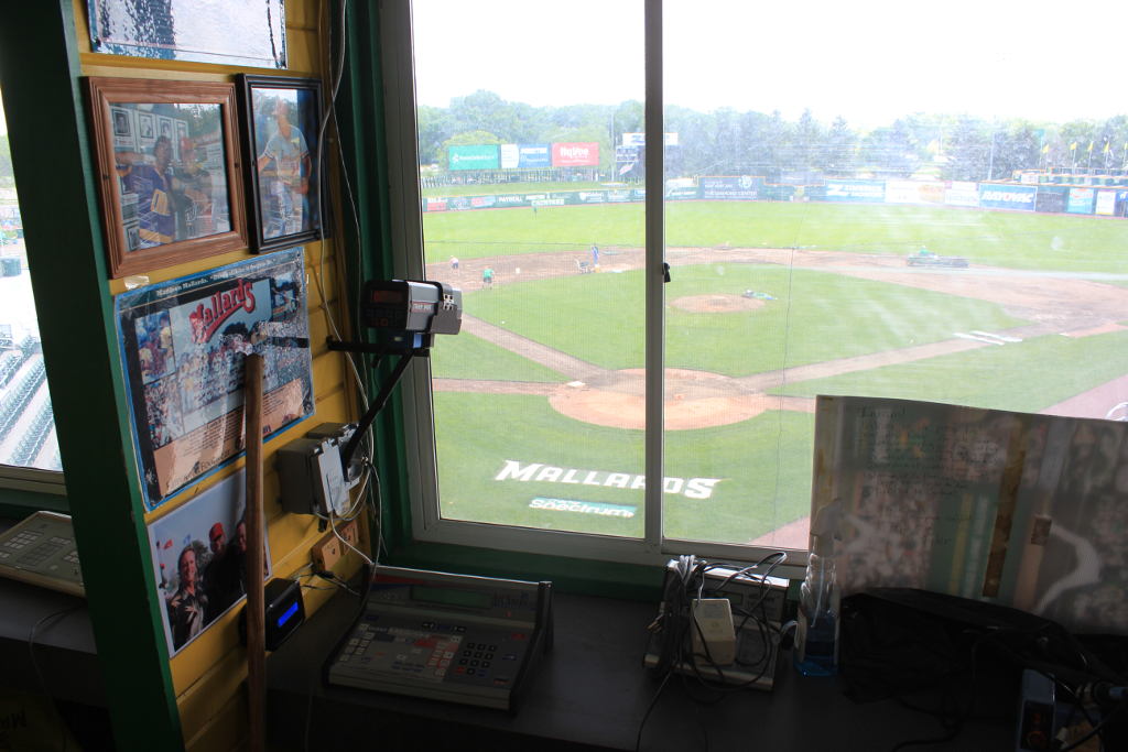
The view from the press box. The radar gun captures every pitch, the controller box is mounted on the wall, and the previous controller is wrapped up on the desk.
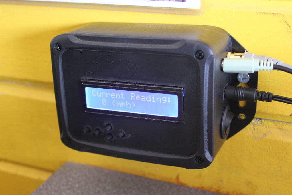
The controller box. There’s a screen, buttons, and power switch. The cables are for power in, power/serial to the radar gun, and RS485 out to the sign.
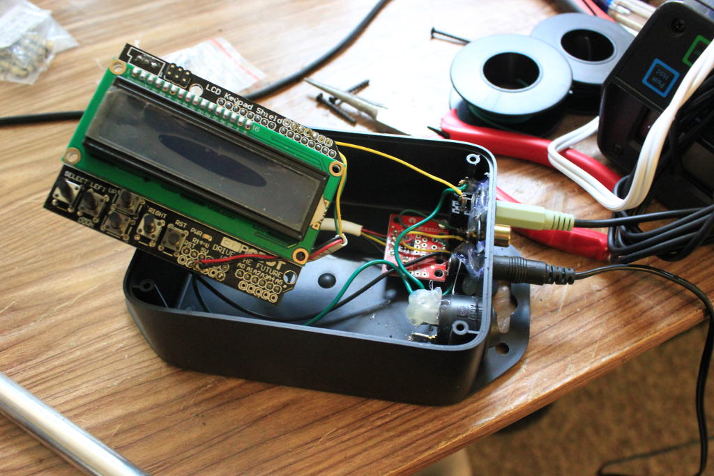
Inside the controller. An arduino with LCD/button shield, a RS485 breakout, and wires.
Next was coming up with a sign. We’ve used the P10 red LED modules before on the bar bike, so we had some experience. For this one we purchased the outdoor waterproof ones. We also got power supplies and a controller card. There is some code on the web for controlling these guys directly, but it’s a lot of work and I didn’t have the time or inclination to figure it out. So we went with the controller card. I should note that the prices for these parts is ridiculously cheap. The LED modules are $6.50, the power supplies are $8, and the controller card was $50. So we had all the major components for the sign for just a few hundred dollars, and that’s because we ordered extras of everything in case of failures. We designed and cut an enclosure and attached the modules to the frame, then wired everything up. The wiring is simple; power up each column, data across each row. Two power supplies power two columns each.
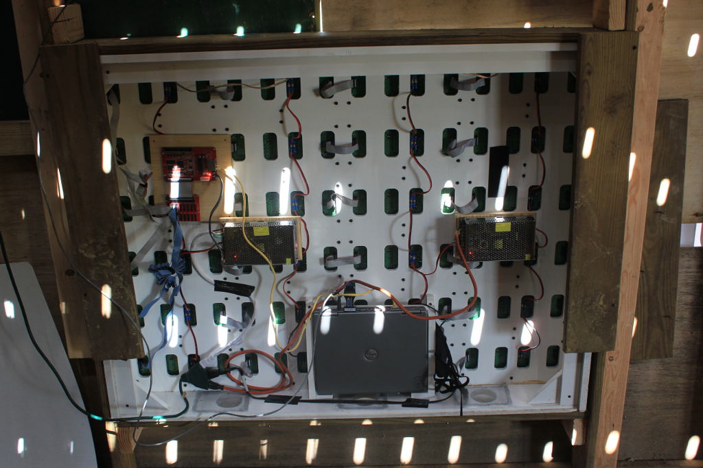
Behind the sign. Two power supplies, one laptop, a controller card and hub, and a laptop. The sign is 6 rows and 4 columns, giving us a resolution of 128×96
Getting the controller card working was tricky, though. There is no documentation on the protocol, so I tried sniffing the packets being sent to it, but couldn’t make sense of them. There was no API, and after repeatedly pressing the Chinese company for resources, they sent some sample code and a dll, but it would only work on windows. We were trying to avoid Windows and go with a cheap (and low power) linux PC or Raspberry Pi, but in the interest of time, we ended up bailing on that and just getting a very old and cheap Windows XP laptop. Fortunately, it had a serial port, so we could hook a RS485 to RS232 converter to it and we were able to communicate quickly with the press box.
The controller card comes with some windows software for setting up the sign and displaying content, but it was difficult to get it to show real time data. What we ended up doing was writing a python script which would monitor the serial port and upon receiving a speed would write that speed to a file. One of the options in the other software for controlling the sign (called LEDSHOWT9), was to display the contents of a file, and update every N seconds. So we picked that option. Now every few seconds LEDSHOWT9 will look at the file, and take the contents (either the speed or a blank), and show that on the sign. Tada! It’s a hack, but it works. If inclined, maybe I’ll write up something better and do animations or something. But probably not.
Here’s the final product.
Clearly visible during the day from the stands. Pretty font, works automatically. Complete success.
This post is about my attempt at a technological solution to gun problems. I built a working prototype, but ultimately I believe that this is not a solution to the problem of mass shootings. There is no technological solution that will prevent someone who is sufficiently motivated from doing significant harm yet still afford us the freedoms that make us human. However, what I built can help prevent people from harming others with weapons sometimes. It has some legitimate circumstances in which it could be very effective.
Background
I was approached by a guy who recognized my wireless communications skills and proposed an idea to me. He had been thinking since the Sandy Hook shooting about how guns could be made safer, and thought that some kind of token that people wore that could disable weapons would be a great solution. Essentially he wanted to create a movement where people carried these tokens that emitted a disable signal, and he thought that governments could be convinced to mandate that all guns listen for this signal and refuse to fire when the disable signal is detected. That was where we started.
Evolution of the idea
Clearly this idea had problems. First was socio-political. Getting a government to mandate this would be impossible, getting people to trade in their guns would be impossible, preventing gun smuggling would be impossible, and establishing exceptions for military and police would be a loophole filled nightmare that would render the system useless. The next problem was technological. A token that’s always emitting a signal would run out of batteries quickly. A weapon that could automatically disable itself would be tricky. And a system that only deactivates if it hears a deactivate signal can easily be foiled by… aluminum foil. Wrapping the gun in aluminum foil would prevent the signal from reaching the antenna.
It took a lot of back and forth to come to a final solution, and it still has flaws. But we’ll get to that later. And I have no way to address the political or social problems; I’m a technical guy and that is a job for someone else. Here’s what we ended up with:
Solution
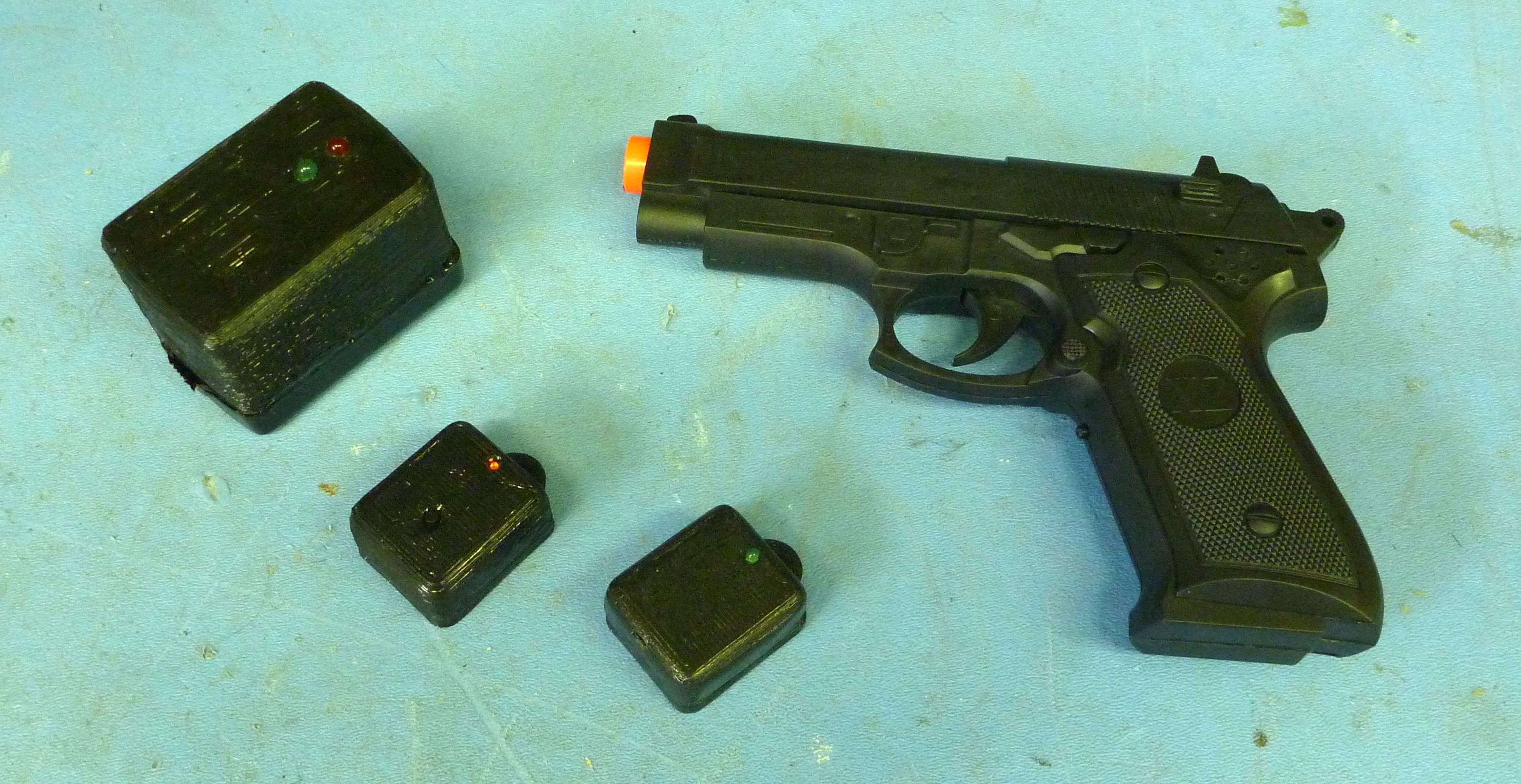
The four parts: the weapon, enable token, disable token, and plugin disable token.
1) An enable token with a button that emits an ‘enable signal’ repeatedly while it’s turned on. We’re using Bluetooth Low Energy because this is exactly the sort of thing BLE was designed for. Low energy wireless communications. The enable token is paired with the weapon so that only that enable token can enable that particular weapon. This means the weapon will not enable unless the enable token is on, and within range. This prevents people from using stolen weapons, or getting into their parents’ guns, or accidentally firing, and can also prevent a gun from being used against its owner. This enable token alone is what makes this system great. There are far more accidental shootings, shootings with stolen weapons, and attacks against the owner than there are mass shootings, and an enable token paired to a gun would prevent a lot of those. But the enable token also serves another important purpose. Remember how you could just wrap a gun in aluminum foil so it doesn’t get any disable signals? Well if the gun needs to hear an enable signal, it can’t do that while covered in aluminum foil. So the fact that the gun has to hear a signal to enable means it must be capable of hearing a signal to disable.
2) The weapon with a receiver (and optionally a transmitter). The weapon has an electromechanical device that is connected between the safety and the firing mechanism. When the safety is diesngaged, this module is powered on, and when it hears the right enable signal, and no disable signals, it will allow the gun to fire. As soon as it hears a disable signal or stops hearing the enable signal, it will disengage and the weapon will not fire.
3) A disable token that emits a ‘disable signal’ every few seconds. Essentially this beacon says to any specially equipped guns “please don’t fire near me.” Any weapon or enable token within range will immediately disable itself. Another advantage of using Bluetooth Low Energy is that many cell phones are now coming with BLE capability built in, which means eventually a cell phone could be emitting this disable beacon. So people wouldn’t need to carry an additional piece of electronics; it would be an app they could download and run in the backgroun
4) Finally, a fourth device can plug into a wall and emit a disable signal regularly. It could also be listening for enable signals that would indicate someone is trying to enable a gun. And if the gun were emitting a signal saying “hey, I’m a gun and someone is trying to fire me” it could listen for that as well. It would have a siren and possibly other ways to indicate authorities that a gun was trying to be used in a certain area.
Building
I ordered some fake guns from Amazon, some Bluetooth modules from BlueGiga, and designed some parts for the enclosures. Writing the software for the Bluetooth modules, building the circuits, 3D printing the parts, assembling it all, and testing it, took a relatively short amount of time. A few weeks, really, and that was just in my spare time. It’s only prototypes, so I wouldn’t want to mass produce them the way I built them, but for a working prototype, it works and looks acceptable.
One thing I skipped was designing the electromechanical part that would prevent a gun from firing. I justified this by saying that many guns would be different in their implementation, and I don’t have a real weapon to develop for, and we were trying to prove the wireless concept.
Problems
Here are a few of the problems I ran into.
Range: Of course, you’re preventing guns that are within range, not bullets. A gun that is sufficiently far that it doesn’t get a disable signal will still be able to fire INTO an area.
Aluminum Foil: It’s still entirely possible to put the enable token INSIDE the aluminum foil surrounding the weapon so that it gets the enable signal and not a disable signal.
Timing: A disable signal should be sent infrequently to conserve battery life, prevent collisions, and keep the airwaves mostly clear. But the longer it is the more opportunity to not hear it. A weapon could be enabled and fired in between disable signals. We tried to get around this by disabling for at least five seconds after hearing a disable signal, but if the weapon is turned on, enabled, and fired before the first disable signal reaches it, there’s at least one bullet getting shot. Yes it prevents further shots, but one is enough to do damage. You can see in the video that the gun is enabled briefly before it receives a disable signal.
Safety: Usually when a gun is being fired, timing is critical, and having to wait for your gun to enable before you can fire it could mean life or death. That’s why it’s critical that the enable happens immediately every time.
Bad guy has a regular gun and a disable token: So he can prevent you from firing, but he is unaffected. Unless the world has 100% adoption of this system, there will be guns that have an edge over other guns, and that makes this system undesirable.
Batteries: Yes, it has batteries. Batteries run out. Then you’re in trouble.
Gunk: When weapons fire, there’s an explosion, and then powder gets all over the place. On guns it’s really hard to keep this powder from getting all over. Further, there’s not a lot of room in a lot of guns for the firing mechanism to attach to the trigger since it has to wrap around the magazine, so it’s a tiny space that could easily get filled with stuff that could prevent it from working.
Benefits
Safety: Guns can only be fired if the enable token is on, which means fewer accidental firings.
Theft deterrence: A gun without its enable token is useless, so the owner (who should still be responsible about protecting his gun), can add protection by keeping his enable token separate from his guns.
More difficult to misuse guns: It’s not a failsafe system, but it adds a layer of security and challenge that may deter some people.
Conclusions
This is my contribution to the conversation. I built something that has the potential to solve some problems for some people. But after developing and considering the situations in which this might not work, and the motivations behind the gun makers, legislators, gun owners, and gun shooters, this system, and any other like it, has too many holes and challenges to make it a cure-all for gun control. We shouldn’t be applying technology like this to guns because it defeats their purpose and doesn’t solve the real problem that exists with the person holding a weapon.
After Erin took me on a ski trip to Salt Lake City for Christmas 2010, I was far behind in the Christmas Karma. For 2011 I planned to take her to a resort in Wisconsin Dells, which is sort of like the Las Vegas of Wisconsin, except with water parks instead of casinos. Of the many resorts, I decided on Kalahari based on recommendations of others and some research on the web. But just telling her wasn’t a great way to do the presentation. I wanted her to unwrap something.
I’ve been working for a while on a portable electronic scoreboard, so I had all the materials to make a good LED sign with the name. The day before we were to leave for Kansas, I started the project. The idea was to make a big LED sign that said Kalahari on it. It would be battery powered, and a switch would turn it on when the box was opened so that it wasn’t on the entire time and running out of battery. That was as far as I got in planning before I started building.
I borrowed a rechargeable battery from Sector67 to use as the power supply, then laid out the LEDs on a prototyping perf board covered with sticky black nylon paper. It took a couple tries to get it all to fit on the available board with legible letters and decent spacing. Then I found a switch that would work. The circuit was simple. The switch connected the + voltage to the board and the ground went directly to the board. The LEDs were connected with a resistor and two LEDs in series, and all those strings were in parallel. This meant a huge current drain, but I was limited to a power supply with only 6 volts, so I didn’t have much choice. This also meant a LOT of soldering and a lot of current limiting resistors. There was an odd number of LEDs, so I put an extra one on the back side so that the circuits were all the same.
With all these LEDs packed into a small space, it was very bright, so I struggled with a few different ways to do the presentation. I ended up taping the board behind a piece of paper so that the paper would diffuse the light a little. It ended up working great. The paper covered everything, including the switch. When the box was closed it was off, and when it was opened the switch was triggered, turning on the sign.
The girlfriend was happy, so the project was a success.
The next time I do something like this I’ll use less LEDs and instead of doing a sign of LEDs I think it would be better to have a piece that had letters cut out and was backlit by only a few LEDs. I also would have spent a lot more time on what was surrounding the sign. Using regular paper and crayon to draw was the best I could do with the limited time and resources I had, but it wasn’t enough for me. Construction took far longer than I expected, and I was a little disappointed with the results. I was working late into the night to solder it all together, and I barely had any time to work on the rest of the package. I can do better.
Since I’m moving in a few months to an apartment of significantly reduced size, I am starting to reduce the size of my collection of stuff. One thing I’ve been carrying around is everything from my college career. I have every syllabus, paper, homework assignment, handout, midterm… in total it was three boxes full of binders. This represents tens of thousands of dollars of education, though, and I wasn’t entirely willing to part with it. I started scanning pages with a scanner. I had a process that was giving me up to 6 scans per minute. The quality of the scans was good, but the speed was not fast enough, and there were too many manual parts to the process. I needed something faster.
I realized that a photo of a piece of paper would be faster than having a scanner do it, and if lit well enough and with a good enough lens, it would be just as good as a scanner. I rigged up a tripod with an extended arm to hold my camera, and I put a white background on the desk and marked some lines where the paper needed to be to be in the shot. Since I don’t have a fancy DSLR with a remote, and pressing the button manually was way too much effort and moved the camera around too much, I rigged up a piece of twine so that by pulling down on the twine I could get the camera to take a shot. I tried pulling the string for a while, which was pretty fast, but still not as efficient as possible. I tied the twine to a ruler and used the ruler as a foot pedal, giving me both hands to move the pieces of paper as quickly as possible. The light sources were just regular white compact fluorescent bulbs, placed to put as much light on the paper as evenly as possible.
The resulting contraption bumped my speed up to 15 pages per minute on average. Sometimes it was higher depending on if I was dealing with loose notes or stapled sheets. Having the shutter controlled by my feet gave me a huge advantage, and I was able to fly through all 3 boxes of papers in a few evenings much faster than I expected. Now I have it all on my computer, which should probably still be sorted, but at least it’s not taking up any physical space, and I don’t have to feel any sense of loss when I recycle my stacks of papers.
Last night I made some changes to my mouse; we’ll see if they’re improvements or not. Originally I was dismantling it to clean it. Something had gotten inside the wheel and was causing it to scroll inconsistently. Once I got inside, though, I saw an opportunity to tune it.
First was the clicking on the wheel. This is accomplished with a spring, and is sometimes annoying, especially since I like to give my scroll wheel big long spins to quickly move around on a page. Removing the spring was pretty easy.
Second, I noticed a weight added to the inside. I’m not entirely sure what the weight accomplishes, other than making the mouse that much harder to move, so I took it out, too.
If I need, I can easily put the parts back in, but at the moment I’m rocking a lighter, smoother mouse.